


LPS-T10
LHY AudioがEversolo T10専用に設計
LPS-T10
デュアルトランスによる完全リニア電源。
Eversolo T10用の内部電源アップグレードキット。
標準位置に適合・外付け筐体不要・筐体の切削不要
T10をさらに高める。電源から始める。

システム全体の電源をアップグレード
電源経路の全段を、ひとつずつ磨く。
LHY Select · recorded reduction at the 3 A test load
LHY Select · main-filter capacitance
電源構成
専用トランス
連携する6つの段
入力フィルターから低ノイズ出力まで。
-
01入力フィルター
2段EMIフィルター
-
02専用トランス
主電源/制御側
-
03理想整流
LT4320全波整流
-
04エネルギー蓄積
バージョン別コンデンサーバンク
-
05リニア安定化
LT3042 + PNP
-
06フィルター済み出力
広帯域+OCC
LHY Select・ラボ測定
The 3 A laboratory high-load test record shows a 94.82% ripple reduction.
Under the same LHY Audio laboratory conditions, with only the power supply changed, the Original T10 PSU measured 61.67 µVrms and LPS-T10 LHY Select measured 3.192 µVrms.


Tested under controlled conditions in the LHY Audio laboratory. Under the same 3 A high-load condition, only the power-supply assembly was changed. The 94.82% figure is the reduction calculated from this test record; readings can fluctuate and the value is not guaranteed.
3つの主要モジュール
3つの主要モジュールで完全リニア構成を実現。
主DC安定化基板、AC入力・補助リニア電源モジュール、T10筐体専用の主トランスを組み合わせています。
電源構成
| 項目 | 標準T10 | LPS-T10 | 設計上の変更 |
|---|---|---|---|
| システム設計 | 標準T10主電源はリニア、ディスプレイ・制御・スタンバイ回路はスイッチング電源。 | LPS-T10主電源側と制御側に専用経路を設けた、デュアルトランスの完全リニア構成。 | 設計上の変更ディスプレイ・制御・スタンバイ回路のスイッチング電源を、専用リニア電源へ置き換えます。 |
主DC電源
DCリニア安定化基板
主電源の整流、エネルギー蓄積、安定化、出力フィルターを担当。
主な特徴
低電圧降下の整流
整流段の順方向電圧降下と、それに伴う損失を抑える設計。
3.19× main-filter capacitance in LHY Select
LHY Select provides 90,000 µF, compared with 28,200 µF in the original supply. The optional Mundorf configuration provides 60,000 µF.
低ノイズのリニア安定化
LT3042レギュレーターとPNP電流ブーストを使用。
広帯域出力フィルター
残留リップルと高周波ノイズに対処する設計。

DCリニア安定化基板
| 項目 | 標準T10 | LPS-T10 | 設計上の変更 |
|---|---|---|---|
| 整流 | 標準T10MUR860高速リカバリー整流ダイオード。 | LPS-T10LT4320による理想ダイオード全波整流。 | 設計上の変更順方向電圧による損失と、それに伴う発熱を抑える設計。 |
| 主フィルター容量 | 標準T10ELNA 4,700 µF / 35 V × 6 · 28,200 µF total. | LPS-T10LHY Select:KEMET 15000µF / 40V×6、計90000µF。Mundorf Version:MLytic AG 10000µF / 40V×6、計60000µF。 | 設計上の変更Approximately 3.19× stock for LHY Select; 2.13× stock for Mundorf Version. |
| 安定化回路構成 | 標準T10OPA277オペアンプとMOSFETによる安定化。 | LPS-T10ADI LT3042超低ノイズリニア安定化+PNP電流ブースト。 | 設計上の変更低ノイズのリニア安定化構成を採用。 |
| 出力フィルター | 標準T10SamYoung 470 µF / 50 V × 30. | LPS-T10Nichicon KZ MUSE 470µF / 25V×6+Panasonic FM 1000µF / 16V×9。 | 設計上の変更残留リップルと高周波ノイズに対処する設計。 |
| 基板と組み立て | 標準T101.6mm厚、無電解金メッキ基板。 | LPS-T102oz銅箔・2.0mm厚の無電解金メッキ基板に、厳選はんだと太い金メッキピンを採用。 | 設計上の変更銅箔を厚くした電源経路と、堅牢な接続部品。 |
オプションのコンデンサー構成
Mundorf Version・追加US$300LHY SelectはKEMETとWIMAのコンデンサーを使用。Mundorfを希望するお客様には、追加US$300で専用DC基板構成を用意しています。
LHY SelectとMundorf Versionはどう選ぶ?
価格と構成のバランスでは、追加料金なしでKEMETとWIMAを使用するLHY Selectをおすすめします。Mundorfを希望する場合は、追加US$300の専用構成を選べます。両構成はLPS-T10の電源構成と出力仕様を共有します。
2つの構成の違いは?
| 部品/仕様 | LHY Select | Mundorf Version・オプション構成 |
|---|---|---|
| 1. 蓄積コンデンサーの定格最高使用温度 | LHY Select85°C | Mundorf125°C |
| Mundorfの蓄積コンデンサーは、定格最高使用温度がより高く設定されています。 | ||
| 2. フィルムコンデンサー容量 | LHY Select0.1µF×4個 | Mundorf0.22 µF 各×4個 |
| Mundorfはフィルムコンデンサー1個当たりの容量が2.2倍で、回路に応じて有効帯域内の高周波干渉をバイパスする助けとなります。 | ||
| 3. フィルムコンデンサー構造 | LHY SelectWIMAポリプロピレン | MundorfMundorfオイル含浸ポリプロピレン |
| Mundorf EVO Aluminium.Oilは、内部振動を抑えるためのオイル含浸巻線構造を採用しています。 | ||
| 4. 蓄積コンデンサー総容量 | LHY Select90,000 µF | Mundorf60,000 µF |
| LHY Select provides greater reservoir capacitance and stores more energy at the same voltage and connection arrangement. | ||
| 5. フィルムコンデンサー定格 | LHY Select1,000 VDC / 105°C | Mundorf450 VDC / 85°C |
| 電圧と温度の定格は、個々のフィルムコンデンサーの使用限界を示します。 | ||
| 6. 追加料金 | LHY Select追加料金なし | Mundorf+US$300 |
| KEMETとWIMAの組み合わせならLHY Select、Mundorfとオイル含浸構造を希望する場合はオプション構成を選べます。 | ||
コンデンサー仕様を比較
| 部品/仕様 | LHY Select | Mundorf Version・オプション構成 |
|---|---|---|
| 構成 | LHY SelectLHY Select | Mundorfオプション構成・追加US$300 |
| 蓄積コンデンサー型番 | LHY SelectKEMET ALC70 · ALC70A153CD040 | MundorfMundorf MLytic AG · MLGO40-10000 |
| 蓄積容量/個数 | LHY Select15,000 µF 各×6個 | Mundorf10000µF×6個 |
| 蓄積コンデンサー定格 | LHY Select40VDC・±20%・最高使用温度85°C | Mundorf40 VDC · ±20% · 125°C 最高使用温度 |
| 蓄積コンデンサー総容量 | LHY Select90,000 µF | Mundorf60,000 µF |
| フィルムコンデンサー型番/構造 | LHY SelectWIMA MKP 10・ポリプロピレンフィルム | MundorfMundorf MCap EVO Aluminium.Oil・MEO-0,22T4.450・オイル含浸メタライズドポリプロピレンフィルム |
| フィルム容量/個数 | LHY Select0.1µF×4個・4個とも同じ大型仕様 | Mundorf0.22 µF 各×4個 |
| フィルムコンデンサー定格 | LHY Select1,000 VDC · ±5% · 105°C 最高使用温度 | Mundorf450 VDC · ±4% ・最高使用温度85°C |
| Nichiconコンデンサー | LHY SelectMUSE KZ · 470 µF / 25 V × 6 | MundorfMUSE KZ · 470 µF / 25 V × 6 |
| Panasonicコンデンサー | LHY SelectFM · 1,000 µF / 16 V × 9 | MundorfFM · 1,000 µF / 16 V × 9 |
| Rectification / 12 V regulation | LHY SelectLT4320理想整流・LT3042+PNP電流ブースト | MundorfLT4320理想整流・LT3042+PNP電流ブースト |
表示温度は個々のコンデンサーの定格最高使用温度です。
Mundorf DC基板を見る
AC入力と補助電源
EMI・リニア入力モジュール
AC入力をフィルターし、ディスプレイ・制御・スタンバイ回路へ専用の補助リニア電源を供給します。
主な特徴
入力側の干渉フィルター
トランスと安定化段の前で、商用電源由来の干渉に対処する設計。
専用の補助リニア電源
ディスプレイ・制御・スタンバイ回路に独立したリニア電源経路を提供。
低抵抗経路を備えたフィルター
コモンモードフィルターと低抵抗の電流経路を組み合わせる設計。
電流と放熱を考慮した設計
電源経路を強化し、電流の供給と熱の拡散に配慮。

EMI・リニア入力モジュール
| 項目 | 標準T10 | LPS-T10 | 設計上の変更 |
|---|---|---|---|
| EMIフィルター構成 | 標準T10標準安全コンデンサーによる基本的な2段コモンモードフィルター。 | LPS-T10RIFA / Eaton X2安全コンデンサーによる2段コモンモードフィルター。 | 設計上の変更トランスと安定化段の前で、商用電源由来の干渉に対処する設計。 |
| 安全コンデンサー | 標準T10標準安全コンデンサー。 | LPS-T10RIFA / Eaton PME271 X2・Y2安全コンデンサー。 | 設計上の変更ACラインのフィルターと干渉抑制のために選んだ認証済み安全部品。 |
| コモンモードチョーク | 標準T10Eコアの小型コモンモードチョーク。 | LPS-T10高透磁率の専用トロイダルコア2個に、太いOFC線を巻いた構造。 | 設計上の変更ACフィルターと低抵抗の電流経路を組み合わせる設計。 |
| 入力電圧選択 | 標準T10リレーによる自動選択。 | LPS-T10Manual 115 V / 230 V terminal selection before power-on. | 設計上の変更A direct terminal path; the correct setting must be confirmed before use. |
| 基板と組み立て | 標準T10標準1.6mm厚、無電解金メッキ基板。 | LPS-T102.5oz銅箔・2.0mm厚の無電解金メッキ基板と厳選はんだ。 | 設計上の変更厚い銅箔が電流供給と熱の拡散を支えます。 |
専用設計の磁気回路
LHY Audio専用主トランス
デュアルトランス構成のうち、主電源を担当します。
主な特徴
T10専用設計
磁気回路、シールド、グラウンドをT10の主電源に合わせて設計。
主電源専用の役割
デュアルトランス構成内で、制御側補助電源とは別に動作します。
1次・2次側シールド
筐体内のシールド設計の一環として、両巻線側にシールドを設けています。
専用グラウンド
トランスのシールド構造に独立したグラウンド経路を組み込んでいます。

LHY Audio専用主トランス
| 項目 | 標準T10 | LPS-T10 | 設計上の変更 |
|---|---|---|---|
| 構造詳細 | 標準T10Eversoloは、閉ループ磁気回路を持つ専用O-Typeトロイダルリニアトランスと説明しています。コア材、巻線構造、詳細な電気仕様は公開されていません。 | LPS-T10Nisshin 0.27 mm silicon-steel core, Rowan UK 7N OFC windings, primary/secondary copper-foil shielding, independent grounding and heat-resistant PTFE leads. | 設計上の変更T10主電源専用の磁気回路とシールド設計。 |
付属部品と取り付け
T10の標準スペース、取り付け位置、コネクターに合わせた設計。
主要モジュールと専用配線は、T10の標準取り付け位置とコネクターに合わせて設計し、外観と操作部を維持します。
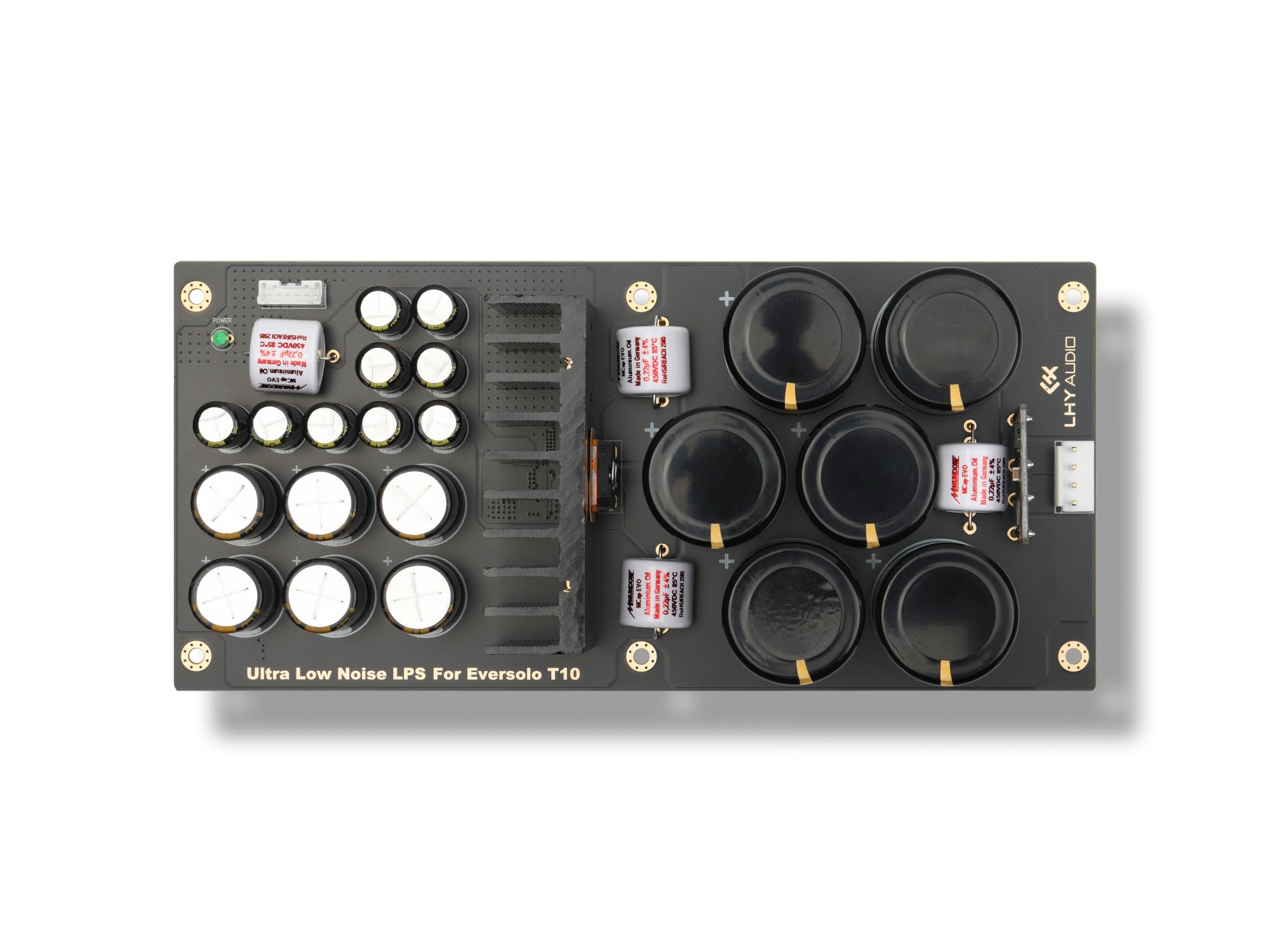
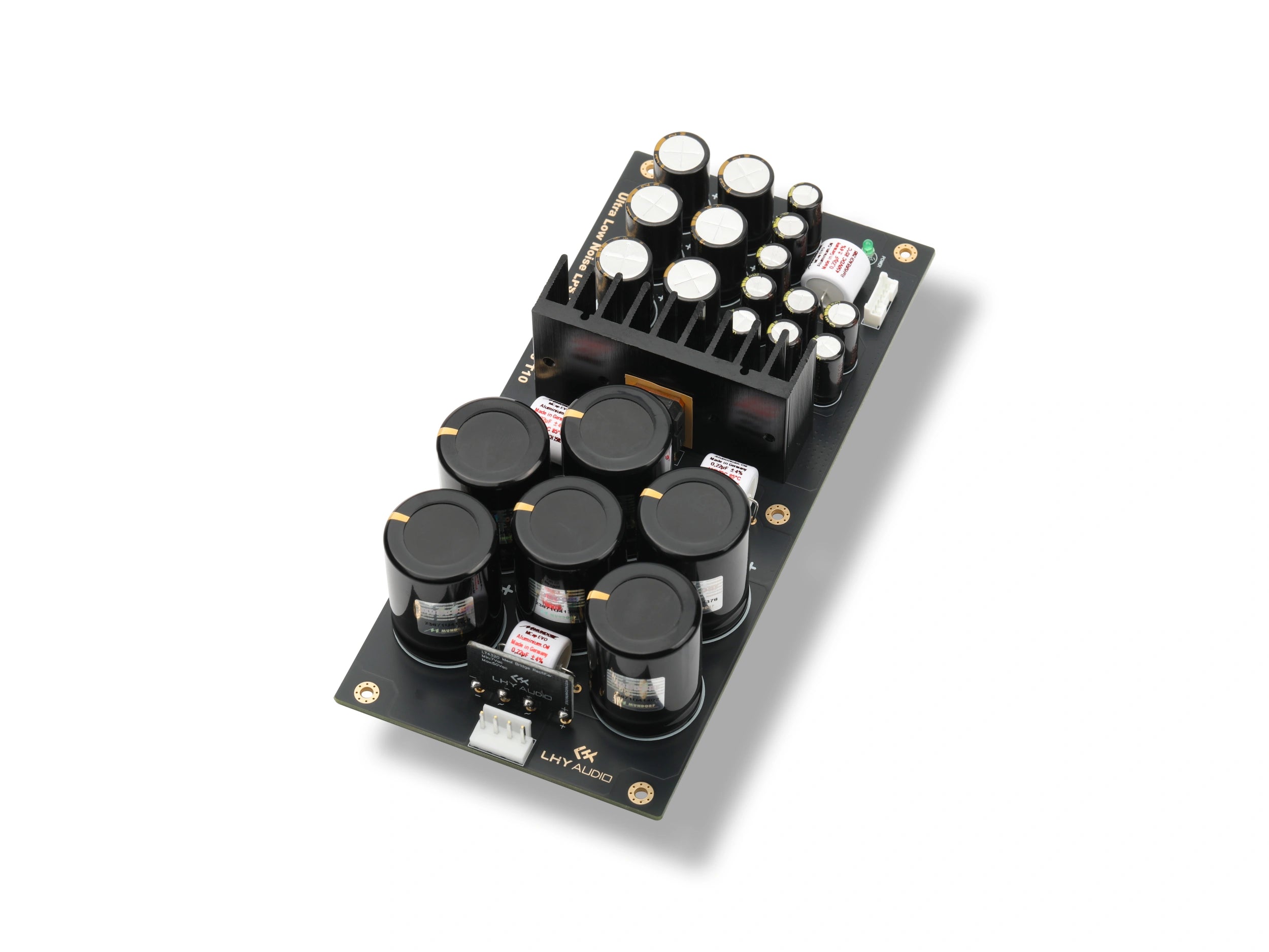
DC安定化基板
選択したバージョンのDC基板:LHY Selectは90000µF、Mundorf Versionは60000µF。画像はLHY Selectです。
EMI・リニア入力モジュール
Talemaを使用した補助電源と2段AC入力フィルター。
専用主トランス
LHY Audio-designed toroidal transformer with 7N OFC windings.

専用内部配線
T10のレイアウトに合わせたOCC出力ケーブルと6ピンフラットケーブル。
標準位置に適合
標準位置に適合。筐体の切削不要。
Installation requires opening the chassis and replacing the power-supply parts at the original mounting points and connectors. No chassis cutting is required, and the exterior and controls remain unchanged.
取り付けガイド(PDF)を見る- 標準の取り付け位置を使用
- 標準の内部コネクターを使用
- 筐体の切削不要
- 外観と操作部を維持
Disconnect mains power and allow sufficient capacitor-discharge time before installation. Before power-on, check the 115 V or 230 V setting against the product label and local mains. If you are unfamiliar with internal installation, use a qualified technician. Internal modification may affect the host warranty.
LHY Select・測定記録
無負荷および3A試験負荷でのµVレベルのリップル。
標準T10とLPS-T10 LHY Selectを、2つのラボ試験条件で比較。
無負荷
At no load, measured ripple falls from 27.65 µVrms to 2.726 µVrms.


3A試験負荷
At the 3 A laboratory test load, measured ripple falls from 61.67 µVrms to 3.192 µVrms.


Measured in the LHY Audio laboratory; within each paired comparison at the same load condition, only the power-supply assembly was changed. The 3 A figure denotes the laboratory test-load condition, not an output specification. Readings can fluctuate with measurement setup and unit tolerance; the percentages shown are calculated from the corresponding test records and are not guaranteed values.
技術仕様
LPS-T10の技術仕様。
よくあるご質問
LPS-T10 よくあるご質問
標準T10電源から何が変わる?
Compared with the original T10, LPS-T10 optimizes the entire power path stage by stage: AC-input filtering, a fully linear architecture, LT4320-based ideal rectification, 90,000 µF in LHY Select or 60,000 µF in Mundorf Version versus the original 28,200 µF, LT3042 + PNP low-noise regulation, wideband output filtering and OCC output wiring. Together, these changes form a complete power-chain upgrade and retain the original chassis integration.
なぜトランスを2つ使う?
The two transformers give each supply path a dedicated role. The LHY Audio-designed 7N OFC transformer serves the main supply, while a Talema transformer with linear regulation powers the display, control and standby circuits. Each path can therefore be designed around its own load. Making the control-side supply linear also removes the original auxiliary switch-mode stage as a potential source of high-frequency switching noise.
How was the 94.82% ripple reduction in the 3 A high-load test record calculated?
These LHY Select records cover two laboratory test conditions: no load and a 3 A high-load condition. At no load, the Original T10 measured 27.65 µVrms and LPS-T10 LHY Select measured 2.726 µVrms; at 3 A, the readings were 61.67 µVrms and 3.192 µVrms respectively. The ripple reduction in the 3 A high-load test record is calculated as (61.67 − 3.192) ÷ 61.67 = 94.82%. Readings may fluctuate and are not guaranteed; 3 A denotes the laboratory test-load condition, not an output specification.
LPS-T10は接続するだけで使える?
LPS-T10 is an internal upgrade kit and requires opening the chassis. Follow the installation guide to disconnect the relevant ribbon cables, remove the original power-supply components, and install the new modules at the original mounting points and connectors. Disconnect mains power and allow sufficient capacitor-discharge time before starting; if you are not comfortable working inside audio equipment, use a qualified technician.
リップルが低ければ、どのシステムでも同じ聴感結果になる?
同じ試験条件では、低いリップルはDC電源に重なる残留AC成分が少ないことを意味し、後段回路への電源ノイズの結合を抑える助けとなります。解像力の高いシステムでは、背景の静けさや微小な細部の明瞭さとして感じられる場合があります。聴感上の変化は、システム全体、商用電源、設置、部屋、聴き手によって異なります。
LPS-T10はEversolo T10向けのアフターマーケット製品です。Eversoloは権利者の商標であり、対応機種を示すためにのみ使用しています。
選択したバージョンには、本ページに記載のコンデンサー構成が付属します。構成を用意できない場合は、在庫切れと表示します。