


LPS-T10
Purpose-built by LHY Audio for Eversolo T10
LPS-T10
Dual-transformer, fully linear power.
An internal power-supply upgrade kit for Eversolo T10.
Original-location fit · no external enclosure · no chassis cutting
Take the T10 further. Start with power.

System-level power upgrade
The entire power chain, refined at every stage.
LHY Select · recorded reduction at the 3 A test load
LHY Select · main-filter capacitance
Power architecture
Dedicated transformers
Six coordinated stages
From input filtering to low-noise output.
-
01Input filtering
Two-stage EMI
-
02Dedicated transformers
Main / control-side
-
03Ideal rectification
LT4320 full-wave
-
04Energy storage
Edition-specific bank
-
05Linear regulation
LT3042 + PNP
-
06Filtered output
Wideband + OCC
LHY Select · laboratory measurement
The 3 A laboratory high-load test record shows a 94.82% ripple reduction.
Under the same LHY Audio laboratory conditions, with only the power supply changed, the Original T10 PSU measured 61.67 µVrms and LPS-T10 LHY Select measured 3.192 µVrms.


Tested under controlled conditions in the LHY Audio laboratory. Under the same 3 A high-load condition, only the power-supply assembly was changed. The 94.82% figure is the reduction calculated from this test record; readings can fluctuate and the value is not guaranteed.
Three core modules
Three core modules form the fully linear architecture.
The system combines a main DC regulator board, an AC input and auxiliary linear module, and a custom main transformer designed around the T10 chassis.
Power architecture
| Feature | Original T10 | LPS-T10 | Engineering change |
|---|---|---|---|
| System design | Original T10Linear main supply with switch-mode power retained for display, control and standby circuits. | LPS-T10Dual-transformer, fully linear architecture with dedicated main and control-side supply paths. | Engineering changeReplaces switch-mode power for the display, control and standby circuits with a dedicated linear supply path. |
Main DC supply
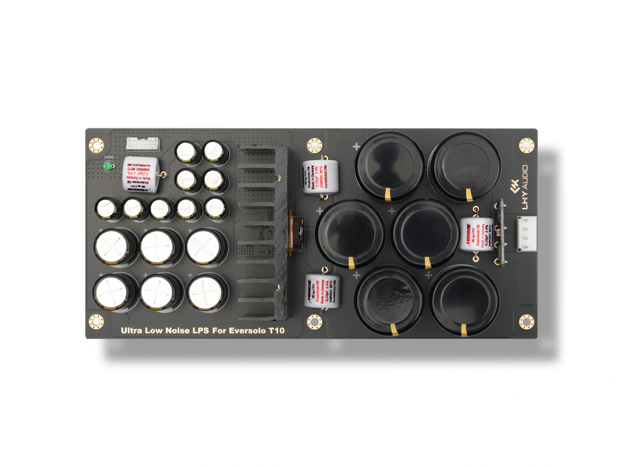
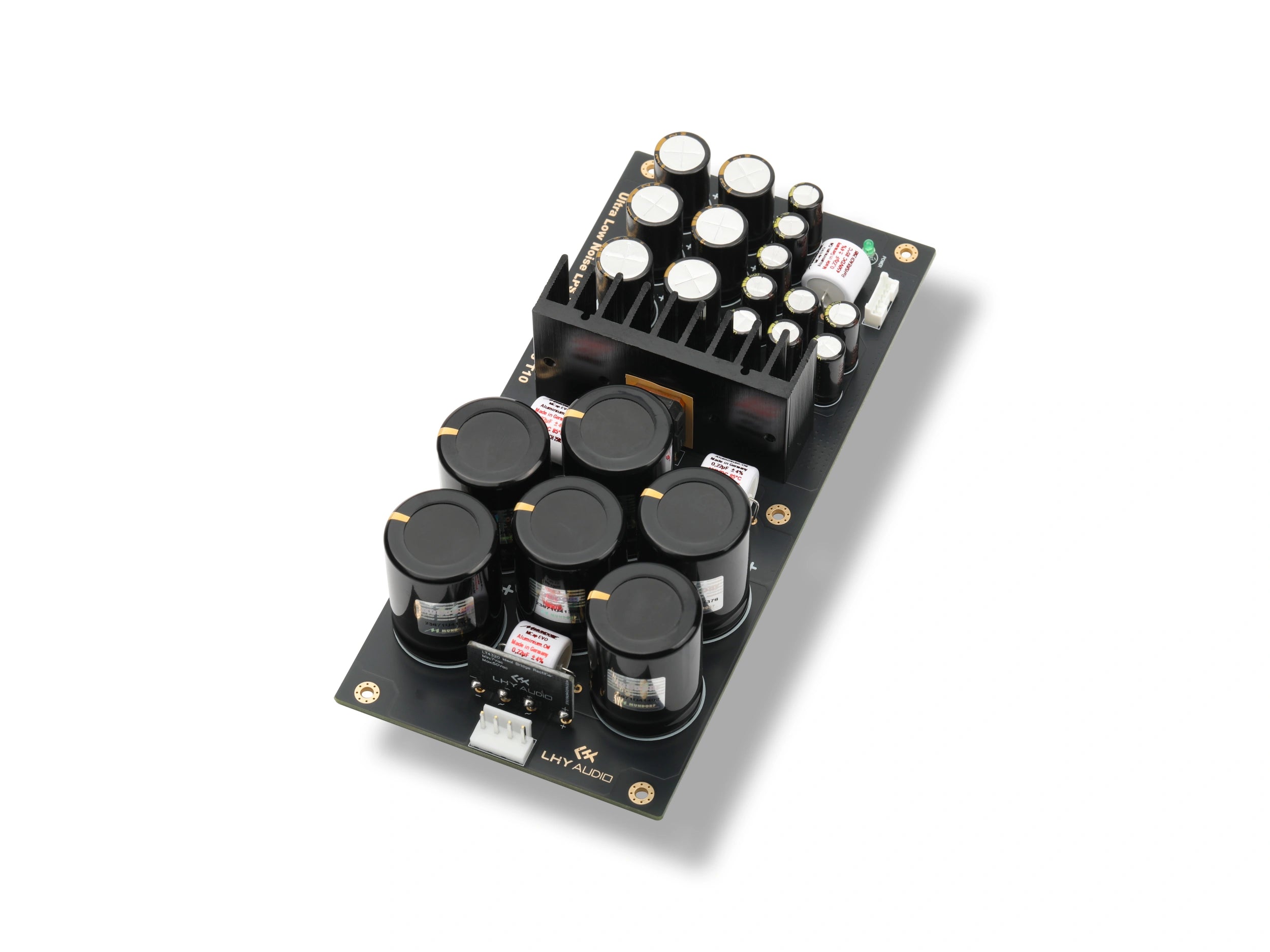
DC Linear Regulator Board
Handles rectification, energy storage, regulation and output filtering for the main supply.
Product highlights
Low-drop rectification
Designed to reduce forward-voltage drop and related dissipation at the rectifier stage.
3.19× main-filter capacitance in LHY Select
LHY Select provides 90,000 µF, compared with 28,200 µF in the original supply. The optional Mundorf configuration provides 60,000 µF.
Low-noise linear regulation
Uses an LT3042 regulator with PNP current expansion.
Wideband output filtering
Designed to address residual ripple and high-frequency noise.

DC Linear Regulator Board
| Feature | Original T10 | LPS-T10 | Engineering change |
|---|---|---|---|
| Rectification | Original T10MUR860 fast-recovery rectifier diodes. | LPS-T10LT4320 full-wave ideal-diode rectification. | Engineering changeDesigned to reduce forward-voltage loss and related dissipation. |
| Main-filter capacitance | Original T10ELNA 4,700 µF / 35 V × 6 · 28,200 µF total. | LPS-T10LHY Select: KEMET 15,000 µF / 40 V × 6 · 90,000 µF. Mundorf Version: MLytic AG 10,000 µF / 40 V × 6 · 60,000 µF. | Engineering changeApproximately 3.19× stock for LHY Select; 2.13× stock for Mundorf Version. |
| Regulation architecture | Original T10OPA277 op-amp with MOSFET regulation. | LPS-T10ADI LT3042 ultra-low-noise linear regulation with PNP current expansion. | Engineering changeUses a low-noise linear-regulation architecture. |
| Output filtering | Original T10SamYoung 470 µF / 50 V × 30. | LPS-T10Nichicon KZ MUSE 470 µF / 25 V × 6 plus Panasonic FM 1,000 µF / 16 V × 9. | Engineering changeDesigned to address residual ripple and high-frequency noise. |
| PCB and assembly | Original T101.6 mm immersion-gold PCB. | LPS-T102 oz copper, 2.0 mm immersion-gold PCB with premium solder and thick gold-plated pins. | Engineering changeA heavier-copper power path with robust connection hardware. |
Optional capacitor configuration
Mundorf Version · +US$300LHY Select uses KEMET and WIMA capacitors. For customers who prefer Mundorf components, a custom DC board configuration is available for an additional US$300.
Should I choose LHY Select or the Mundorf Version?
For the best value, we recommend LHY Select, which uses KEMET and WIMA capacitors with no additional charge. For customers who prefer Mundorf capacitors, a custom configuration is available for an additional US$300. Both configurations share the same LPS-T10 power architecture and output specification.
How do the two configurations differ?
| Component / specification | LHY Select | Mundorf Version · custom option |
|---|---|---|
| 1. Reservoir temperature rating | LHY Select85°C | Mundorf125°C |
| Mundorf reservoir capacitors offer a wider rated operating-temperature range. | ||
| 2. Film capacitance | LHY Select0.1 µF each × 4 | Mundorf0.22 µF each × 4 |
| Mundorf uses 2.2× the capacitance per film capacitor, which can help bypass high-frequency interference within its effective range, depending on the circuit. | ||
| 3. Film construction | LHY SelectWIMA polypropylene | MundorfMundorf oil-impregnated polypropylene |
| Mundorf EVO Aluminium.Oil uses an oil-impregnated winding designed to damp internal vibration. | ||
| 4. Total reservoir capacitance | LHY Select90,000 µF | Mundorf60,000 µF |
| LHY Select provides greater reservoir capacitance and stores more energy at the same voltage and connection arrangement. | ||
| 5. Film capacitor ratings | LHY Select1,000 VDC / 105°C | Mundorf450 VDC / 85°C |
| These voltage and temperature ratings describe the operating limits of the individual film capacitors. | ||
| 6. Additional cost | LHY SelectNo additional charge | Mundorf+US$300 |
| Choose LHY Select for the KEMET and WIMA combination, or the custom option if you prefer Mundorf capacitors and oil-impregnated construction. | ||
Compare capacitor specifications
| Component / specification | LHY Select | Mundorf Version · custom option |
|---|---|---|
| Configuration | LHY SelectLHY Select | MundorfOptional custom configuration · +US$300 |
| Reservoir capacitor model | LHY SelectKEMET ALC70 · ALC70A153CD040 | MundorfMundorf MLytic AG · MLGO40-10000 |
| Reservoir capacitance / quantity | LHY Select15,000 µF each × 6 | Mundorf10,000 µF each × 6 |
| Reservoir capacitor ratings | LHY Select40 VDC · ±20% · 85°C upper operating temperature | Mundorf40 VDC · ±20% · 125°C upper operating temperature |
| Total reservoir capacitance | LHY Select90,000 µF | Mundorf60,000 µF |
| Film capacitor model / construction | LHY SelectWIMA MKP 10 · polypropylene film | MundorfMundorf MCap EVO Aluminium.Oil · MEO-0,22T4.450 · oil-impregnated metallized polypropylene film |
| Film capacitance / quantity | LHY Select0.1 µF each × 4 · all four use the same large-format specification | Mundorf0.22 µF each × 4 |
| Film capacitor ratings | LHY Select1,000 VDC · ±5% · 105°C upper operating temperature | Mundorf450 VDC · ±4% · 85°C upper operating temperature |
| Nichicon capacitors | LHY SelectMUSE KZ · 470 µF / 25 V × 6 | MundorfMUSE KZ · 470 µF / 25 V × 6 |
| Panasonic capacitors | LHY SelectFM · 1,000 µF / 16 V × 9 | MundorfFM · 1,000 µF / 16 V × 9 |
| Rectification / 12 V regulation | LHY SelectLT4320 ideal rectification · LT3042 + PNP current boost | MundorfLT4320 ideal rectification · LT3042 + PNP current boost |
Temperature values shown are the rated upper operating temperatures of the individual capacitors.
View the Mundorf DC board
AC input and auxiliary supply
EMI & Linear Input Module
Filters the AC input and provides dedicated linear auxiliary power for the display, control and standby circuits.
Product highlights
Front-end interference filtering
Designed to treat line-borne interference before the transformer and regulator stages.
Dedicated linear auxiliary supply
Provides a separate linear supply path for display, control and standby circuits.
Filtering with a low-resistance path
Designed to combine common-mode filtering with a low-resistance current path.
Current and thermal design
The heavier power path is designed for current handling and thermal spreading.

EMI & Linear Input Module
| Feature | Original T10 | LPS-T10 | Engineering change |
|---|---|---|---|
| EMI filter architecture | Original T10Basic two-stage common-mode filtering with standard safety capacitors. | LPS-T10Two-stage common-mode filtering with RIFA / Eaton X2 safety capacitors. | Engineering changeDesigned to treat line-borne interference before the transformer and regulator stages. |
| Safety capacitors | Original T10Standard safety capacitors. | LPS-T10RIFA / Eaton PME271 X2 and Y2 safety capacitors. | Engineering changeCertified safety components selected for AC-line filtering and suppression. |
| Common-mode chokes | Original T10E-core, compact-wound common-mode chokes. | LPS-T10Two custom high-permeability toroidal cores with heavy-gauge OFC windings. | Engineering changeDesigned to combine AC filtering with a low-resistance current path. |
| Input-voltage selection | Original T10Automatic relay selection. | LPS-T10Manual 115 V / 230 V terminal selection before power-on. | Engineering changeA direct terminal path; the correct setting must be confirmed before use. |
| PCB and assembly | Original T10Standard 1.6 mm immersion-gold PCB. | LPS-T102.5 oz copper, 2.0 mm immersion-gold PCB with premium solder. | Engineering changeHeavy copper supports current handling and thermal spreading. |
Purpose-built magnetic foundation
LHY Audio Custom Main Transformer
Serves the main supply as part of the system’s dual-transformer architecture.
Product highlights
Purpose-built for T10
The magnetic path, shielding and grounding are designed around the T10 main supply.
Dedicated main-supply role
Works separately from the control-side auxiliary supply within the dual-transformer architecture.
Primary and secondary shielding
Shielding is applied to both winding sides as part of the in-chassis shielding design.
Dedicated grounding
A separate grounding path is integrated with the transformer’s shielding structure.

LHY Audio Custom Main Transformer
| Feature | Original T10 | LPS-T10 | Engineering change |
|---|---|---|---|
| Construction details | Original T10Eversolo specifies a custom O-Type toroidal linear transformer with a closed-loop magnetic design; core material, winding construction and detailed electrical specifications are not disclosed. | LPS-T10Nisshin 0.27 mm silicon-steel core, Rowan UK 7N OFC windings, primary/secondary copper-foil shielding, independent grounding and heat-resistant PTFE leads. | Engineering changePurpose-built magnetic and shielding design for the T10 main supply path. |
Supporting parts & installation
Designed around the T10’s original space, mounting points and connectors.
The core modules and prepared wiring are designed around the original T10 mounting positions and connectors, keeping the exterior and controls unchanged.
DC regulator board
DC board supplied in the selected edition: 90,000 µF LHY Select or 60,000 µF Mundorf Version. LHY Select pictured.
EMI & linear input module
Talema-powered auxiliary rails with two-stage AC input filtering.
Custom main transformer
LHY Audio-designed toroidal transformer with 7N OFC windings.

Prepared internal wiring
OCC output cable set and 6-pin ribbon cables for the T10 layout.
Factory-location fit
Original-location fit. No chassis cutting.
Installation requires opening the chassis and replacing the power-supply parts at the original mounting points and connectors. No chassis cutting is required, and the exterior and controls remain unchanged.
View installation guide (PDF)- Uses the original mounting points
- Connects through the original internal connectors
- No chassis cutting required
- Exterior and controls remain unchanged
Disconnect mains power and allow sufficient capacitor-discharge time before installation. Before power-on, check the 115 V or 230 V setting against the product label and local mains. If you are unfamiliar with internal installation, use a qualified technician. Internal modification may affect the host warranty.
LHY Select · measurement record
Microvolt-level ripple at no load and at the 3 A test load.
Original T10 and LPS-T10 LHY Select are shown under two laboratory test conditions.
No load
At no load, measured ripple falls from 27.65 µVrms to 2.726 µVrms.


3 A test load
At the 3 A laboratory test load, measured ripple falls from 61.67 µVrms to 3.192 µVrms.


Measured in the LHY Audio laboratory; within each paired comparison at the same load condition, only the power-supply assembly was changed. The 3 A figure denotes the laboratory test-load condition, not an output specification. Readings can fluctuate with measurement setup and unit tolerance; the percentages shown are calculated from the corresponding test records and are not guaranteed values.
Technical specifications
LPS-T10 technical specifications.
Questions, answered
LPS-T10 FAQ
What changes compared with the original T10 power supply?
Compared with the original T10, LPS-T10 optimizes the entire power path stage by stage: AC-input filtering, a fully linear architecture, LT4320-based ideal rectification, 90,000 µF in LHY Select or 60,000 µF in Mundorf Version versus the original 28,200 µF, LT3042 + PNP low-noise regulation, wideband output filtering and OCC output wiring. Together, these changes form a complete power-chain upgrade and retain the original chassis integration.
Why use two transformers?
The two transformers give each supply path a dedicated role. The LHY Audio-designed 7N OFC transformer serves the main supply, while a Talema transformer with linear regulation powers the display, control and standby circuits. Each path can therefore be designed around its own load. Making the control-side supply linear also removes the original auxiliary switch-mode stage as a potential source of high-frequency switching noise.
How was the 94.82% ripple reduction in the 3 A high-load test record calculated?
These LHY Select records cover two laboratory test conditions: no load and a 3 A high-load condition. At no load, the Original T10 measured 27.65 µVrms and LPS-T10 LHY Select measured 2.726 µVrms; at 3 A, the readings were 61.67 µVrms and 3.192 µVrms respectively. The ripple reduction in the 3 A high-load test record is calculated as (61.67 − 3.192) ÷ 61.67 = 94.82%. Readings may fluctuate and are not guaranteed; 3 A denotes the laboratory test-load condition, not an output specification.
Is LPS-T10 plug-and-play?
LPS-T10 is an internal upgrade kit and requires opening the chassis. Follow the installation guide to disconnect the relevant ribbon cables, remove the original power-supply components, and install the new modules at the original mounting points and connectors. Disconnect mains power and allow sufficient capacitor-discharge time before starting; if you are not comfortable working inside audio equipment, use a qualified technician.
Does lower ripple guarantee the same audible result in every system?
Under the same test conditions, lower ripple means less residual AC riding on the DC supply, which can help reduce the opportunity for power-supply noise to couple into downstream circuitry. In some highly resolving systems, this may be perceived as a quieter background and clearer low-level detail. The audible degree will still vary with the complete system, mains quality, setup, room and listener.
LPS-T10 is an aftermarket upgrade product designed for use with Eversolo T10. Eversolo is a trademark of its owner and is referenced only to identify compatibility.
Your selected version is supplied with the capacitor configuration listed on this page. If that configuration is unavailable, the version will be marked as out of stock.